


ADD TO BASKET
Product Description
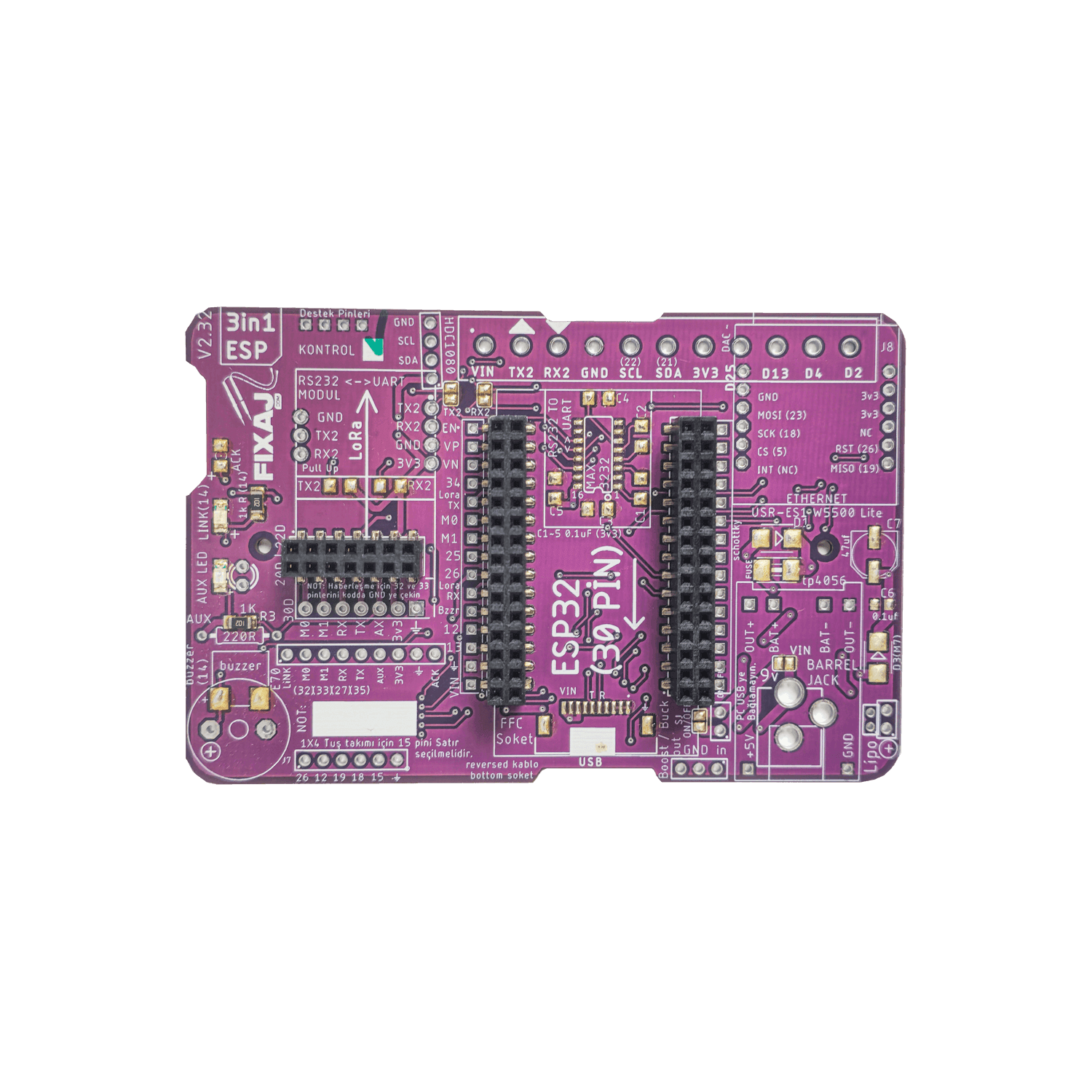
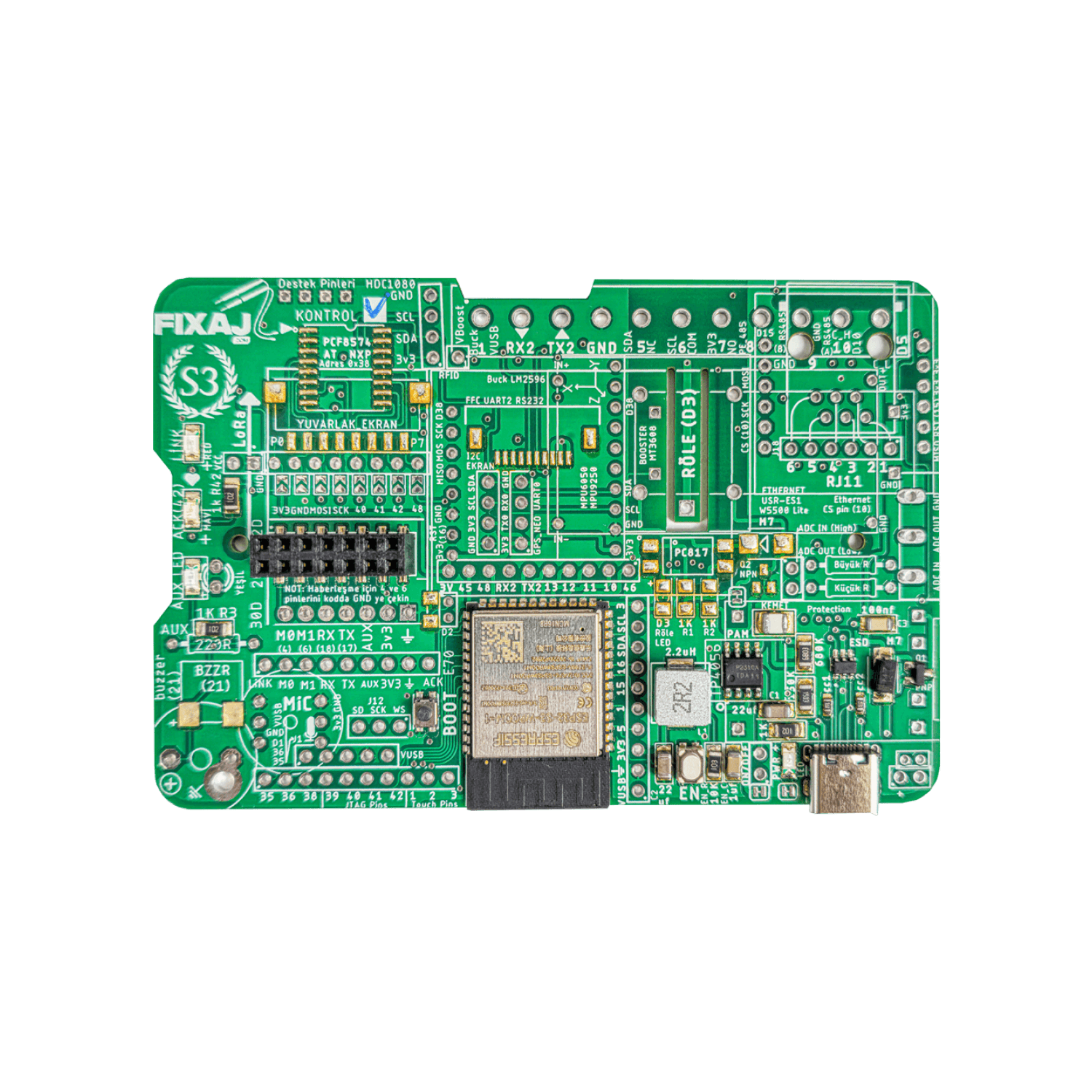
About 3in1 PCB
One of the main assignments of the 3in1 PCB is to use the LoRa wireless communication system, which is the technology of the "future". Thanks to this PCB, there will be no need for cables in data transfer and signal transportation. Since our PCBs are ready to use, you can start using them immediately as you plug the modules and start using them without further modifications.
You can use this technology under various settings varying from agriculture to health, from industry to home automation, from distence calculating technologies to security systems and cell phones. You can use this reliable PCB for any kind of projects you can imagine without worrying.
While designing this PCB, we evaluated the feedback and requests from our customers and made as many scenarios as possible work with the same PCB.
3in1 PCB Use Cases:
+ USB Stick for Lora Parameter Settings
+ Data Exchange with Lora modules
+ Lipo Battery
+ Rs232
+ Rs485
+ HMI with FFC socket
+ HMI with Tunic Socket
+ Arduino NANO iot 33
+ Buzzer
+ Power LED
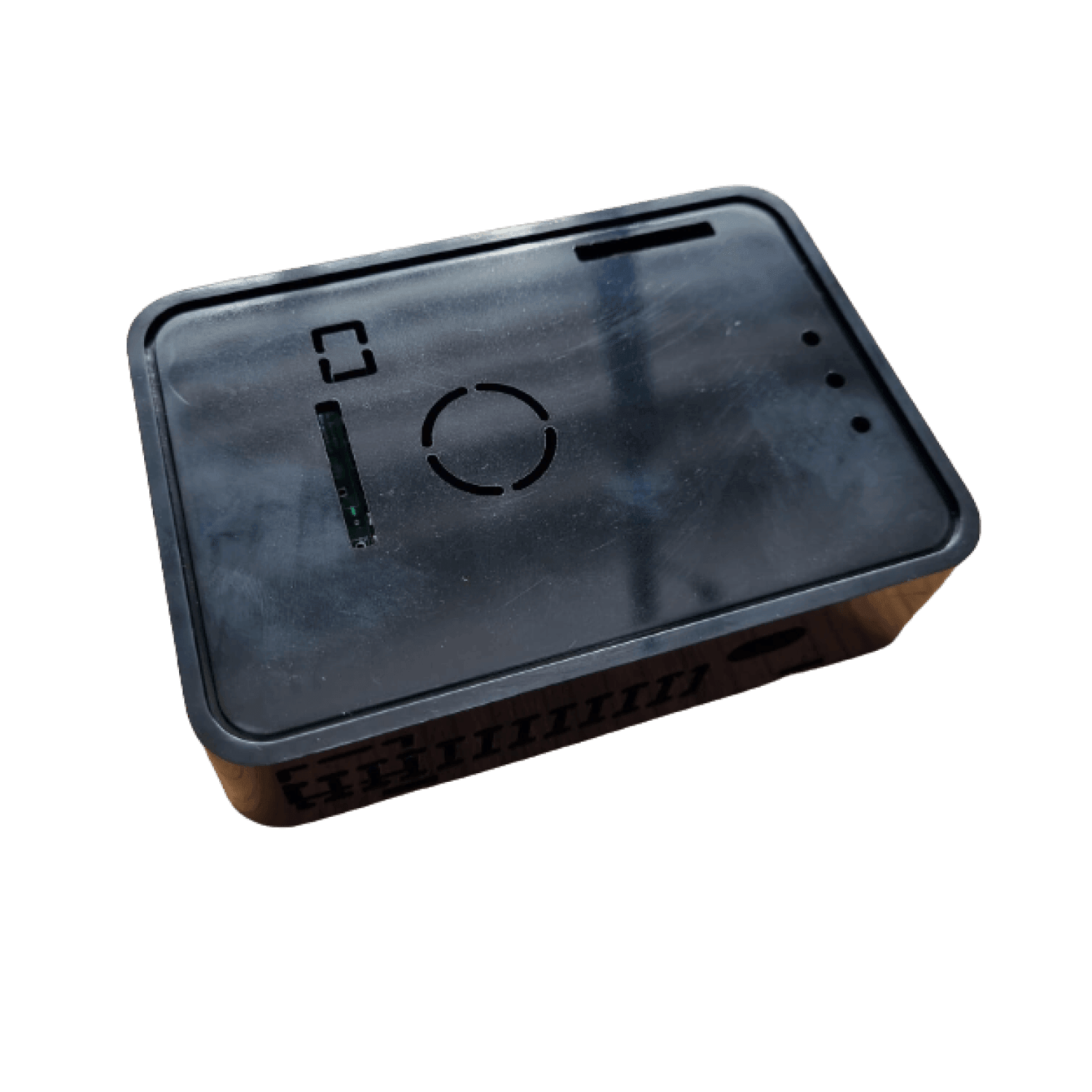
+ PCB Placement in the Box
+ Terminal Connections
You can read the details of the usage methods in the User Manual:
https://docs.google.com/document/d/1DUTOra8AHN7GtLGie8BWLHaHXihbHz27QvQOyAf4PIM/edit?usp=sharing
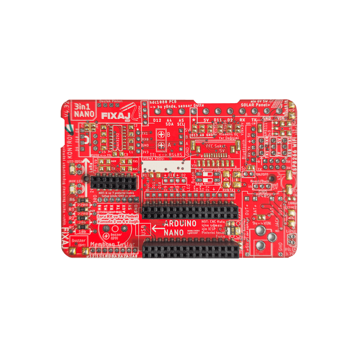
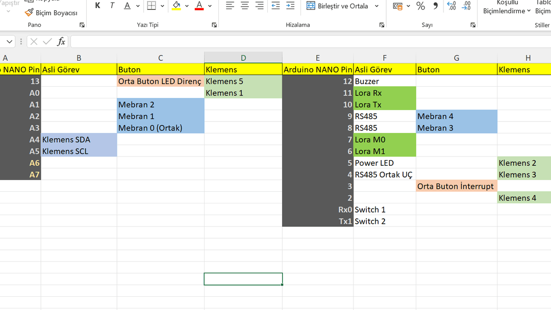
Pins Used on PCB and Their Assigned Tasks
Using the 3in1 PCB as a USB stick
Upload the following code on the Arduino you attached to the PCB:
1 2 3 4 5 6 7 8 9 10 11 12 13 14 15 16 17 18 19 20 21 22 23 24 25 26 27 | #include <SoftwareSerial.h>SoftwareSerial fixSerial(3, 4); // RX, TX PCB versiyon 4.3 sonra bu şekil#define M0 7#define M1 6void setup() { Serial.begin(9600); fixSerial.begin(9600); pinMode(M0, OUTPUT); pinMode(M1, OUTPUT); digitalWrite(M0, LOW); // E22 Modülleri için Aktif edin //digitalWrite(M0, HIGH); // E32 Modülleri için Aktif edin digitalWrite(M1, HIGH);}void loop() { if (Serial.available()) { fixSerial.write(Serial.read()); } if (fixSerial.available()) { Serial.write(fixSerial.read()); }}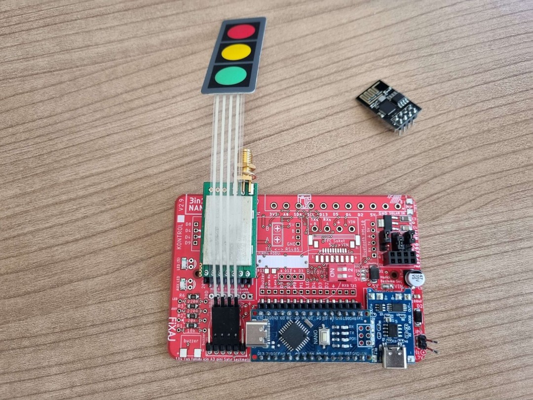 USAGE VIDEO |

There are no comments for this product yet.