Image
Image
Image
ESP32 DevKit 3in1 Expansion PCB, Soldered, Ready to use

Fixaj

ESP32 DevKit 3in1 Expansion PCB, Soldered, Ready to use

Share:
Buy Now
featuresFree Shipping over 200$
featuresBest Price
ADD TO BASKET
Product Description

I will try to explain how to use and what features our newly designed 3in1 ESP PCB offers on this page.
As you already know, Arduino NANO and UNO families are no longer sufficient for some tasks. Due to high demand for Arduinos, the dollar-based price of the product is increasing every day. New and much more powerful ESP32 modules are emerging rapidly in this regard. The widespread use, much cheaper price compared to Arduinos, and extensive ready-made code and library availability inspired me to design a new PCB based on ESP32.
With our 3in1 ESP PCBs, you can easily use LoRa modules and even set up a powerful central server with ETHERNET and FFC outputs.


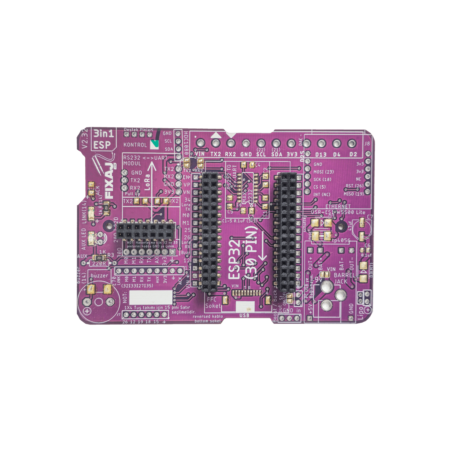
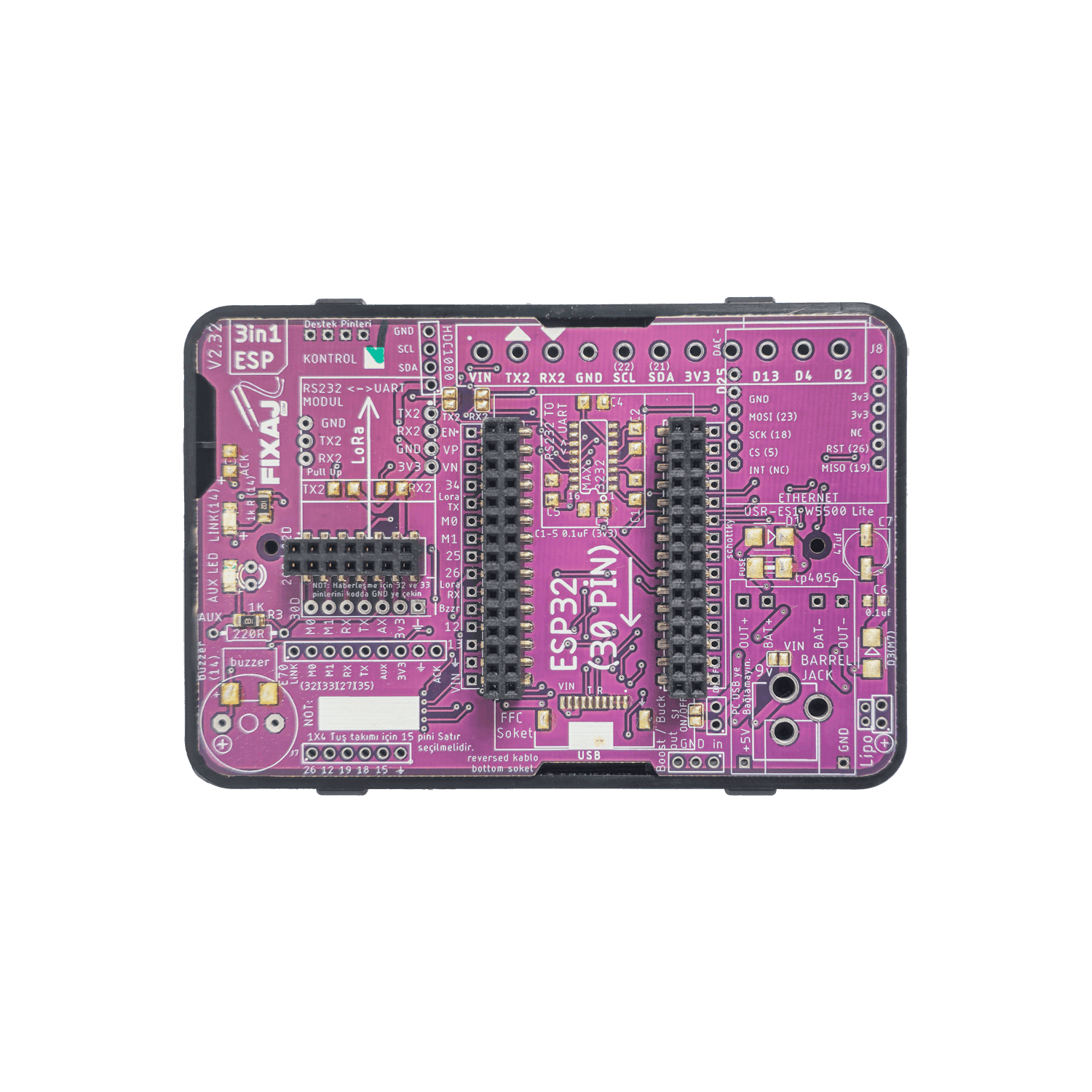
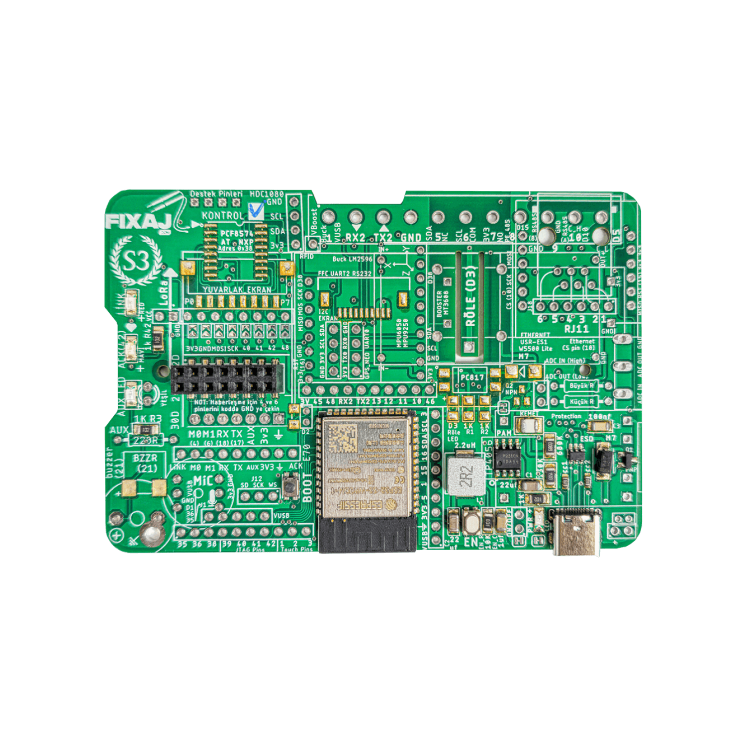
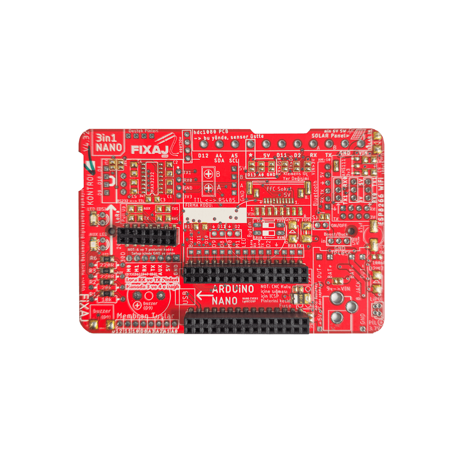
Features of 3 in 1 PCB

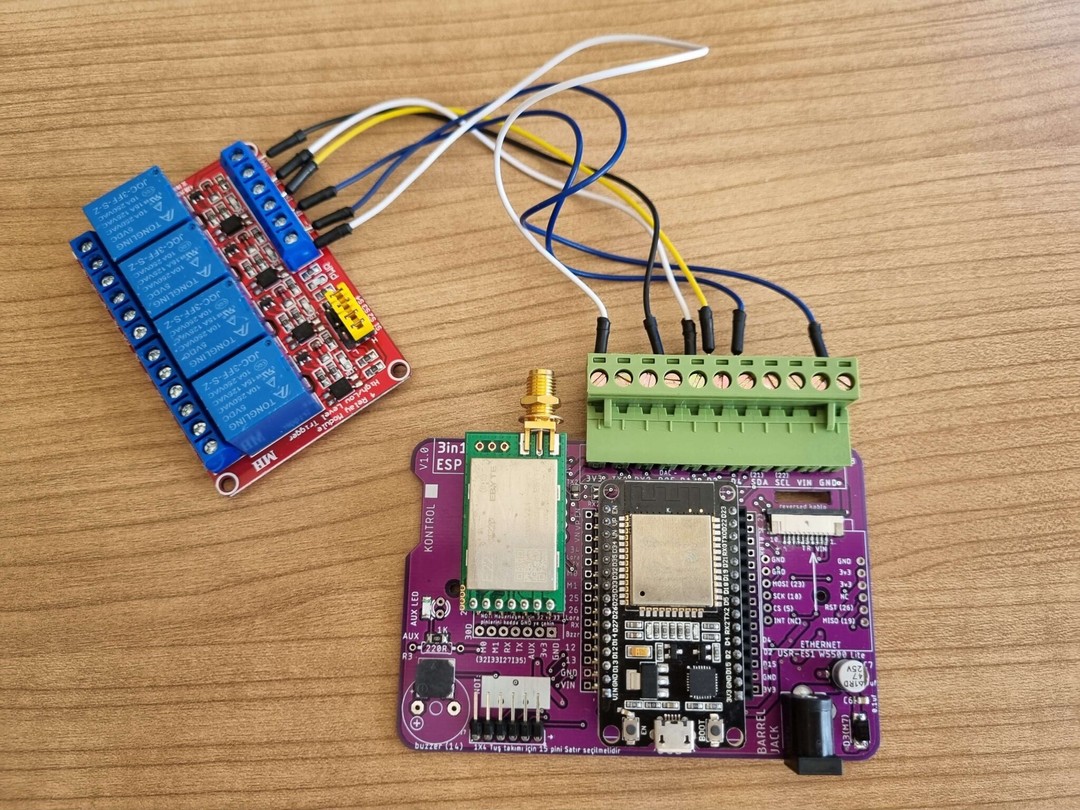
Our 3in1 ESP PCB normally comes with soldered sockets. You can easily attach your ESP32 (30 pin) and E22 or E32 LoRa modules and start wireless communication. The main function of this PCB is wireless communication with LoRa. While communicating with LoRa, I have worked extensively to enable communication via the ESP32's Serial1 port. This way, you can freely use the other 2 UART serial communication pins offered by ESP. Especially transferring Serial 1 port to the LoRa module took a lot of my time. After long-term testing, it is now working successfully. I could have used RX2 and TX2 pins for ease, but if I had done so, you would have been deprived of the other UART pins. I left Serial2 for you, so you can easily attach modules such as touchscreens.


    Other features include:

      • ETHERNET PORT
      • RS232 support
      • Power supply with adapter (max 9v, ideally 5v)
      • Terminal outputs for I2C
      • Buzzer and LEDs
      • Socket for FFC HMI screens
      • 4-pin output for interrupt

    Places that pins of ESP32 is located on our PCB

    3in1 ESP PCB Usage Video

    With our RFSettings Program You Don't Need a USB Stick for Settings

    You can directly give the settings on your code:

    https://github.com/fixajteknik/YouTube_Tutorials/blob/main/Video%2089%20Derinlemesine%20E70/Node_Nokta_e70_Genel_Ok/Node_Nokta_e70_Genel_Ok.ino


    Comments
    There are no comments for this product yet.